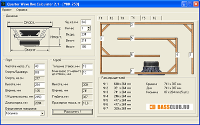
Quarter Wave Box Calculator

Ahh, the good old quarter wave ground plane! This calculator can be used to design a Quarter Wave Ground Plane antenna, with radials.
Over the past 15 years, I have built a number of closed and ported box. The newest versions of the MathCad worksheets are based on a calculation algorithm.
The radiating element is a quarter wave (λ/4) and the radials are 12% longer. There are usually four radials, three being a minimum, but you could use up to six. This is a true unbalanced antenna, with a feed impedance of around 50Ω and therefore a great match to 50Ω unbalanced feedline. The velocity factor is set to 95% which should be fine for most people. Sohraneniya dlya 3d instruktor 227 domashnyaya versiya. You could cut a little on the large side and trim the antenna for best match at your desired frequency if you have the equipment. These antennas can easily be built for UHF or above by using a chassis mount N-Type (or SO-239) connector, some solid wire and solder.
For VHF and below, as the elements get bigger, some more structured design is needed.  A quarter wave monopole mounted against a perfect ground will have an impedance of around 36Ω but by bending the radials down at an angle of 45°, we increase this to around 50Ω whilst at the same time lowering the radiation angle more towards the horizon. (42° is the theoretical perfect angle for 50Ω feed, but who’s measuring!) I have made quite a few of these antennas over the years with good results. They are very forgiving due to the low impedance feed.
I use one at home on 70MHz, to see construction details and more images. The next two images show one I built for the 70cm band. It is good for use between 430-440MHz. It uses 6mm aluminium tube for the radials, 4mm brass tube for the driven element and is built around an N-Type chassis socket mounted to a 40x40mm aluminium square, held together with rivets.
Quarter Wavelength Loudspeaker Design Quarter Wavelength Loudspeaker Design by Martin J. King, 7/17/2002 (last revised 1/27/2019) Welcome to my quarter wavelength loudspeaker design website.
The most common example of a loudspeaker that relies on a quarter wavelength acoustic standing wave is a transmission line enclosure. This style of loudspeaker has been on the fringe of the audio mainstream for many years with just a few smaller companies building and marketing this enclosure design. Even more exotic and rare in the audio marketplace are the TQWT and the horn loaded enclosure designs. All of these enclosures utilize acoustic standing waves that can be described as multiples of a quarter cycle of a sine or cosine function.
Hence my terminology of a 'Quarter Wavelength Loudspeaker Design' to describe the content of the articles contained in this website. I have been interested in transmission line loudspeakers for almost 25 years. However, for a long time the lack of a proven mathematical model prevented me from actually pursuing and building this style of loudspeaker enclosure. Over the past 15 years, I have built a number of closed and ported box loudspeakers based on the equivalent circuit models descibed by Thiele and Small. About 15 years ago, I decided to try and develop my own mathematical model to simulate transmission line loudspeakers using the MathCad computer program. This decision set off the chain of events that eventually resulted in this website. My first two quarter wavelength style enclosures were designed mathematically, built, and then final acoustic and impedance measurements were performed.
During the process of completing these two loudspeakers, the MathCad models went through a continuous evolution which produced more accurate calculated results leading to better correlations between the predictions and the measurements. Recently, I started building a third type of quarter wavelength enclosure that is difficult for me to classify. From the outside it would appear to be a bass reflex enclosure.